The left header has been moving along at a glacial pace, but the heatwave has sped things up. Using the icengineworks model as a guide, the first step was to cut, deburr, brush and tack weld both the left and right sides of the four primaries that cross under the pan. They were left loose in the the flanges on the heads and under the oil pan. Once that was completed the remaining two primaries on the left side were cut and tacked. As previously mentioned, the iceengineworks tack welding clamps are extremely useful during this process. Each runner was removed and finish welded on the bench.
Left header primaries finish welded. The bulges where it might appear that the tubes aren’t concentric are where the tube steps up from 1-7/8” to 2”
The tubes running under the oil pan were kept long up to this point so they were reinstalled and after measuring ten times they were removed and cut to perfectly center the bottom flange on the dry sump pan. The runners were reinstalled and tacked to the exhaust flange and to the flange under the oil pan. The cast exhaust flanges only span two primaries, so a temporary stainless steel rod was tack welded to the top of the flanges to maintain their orientation during final welding (the primaries prevented tacking a rod to the bottom of the flanges).
Although the primaries were only tacked, the header was now a single piece for the first time and we attempted to remove it… NFW. We knew that the headers would most likely need to be removed with the engine, but we were hoping to get lucky. So, I’m in good company with lots of Ferrari’s, Lamborghinis and other exotic cars. In any event, the engine came out again.

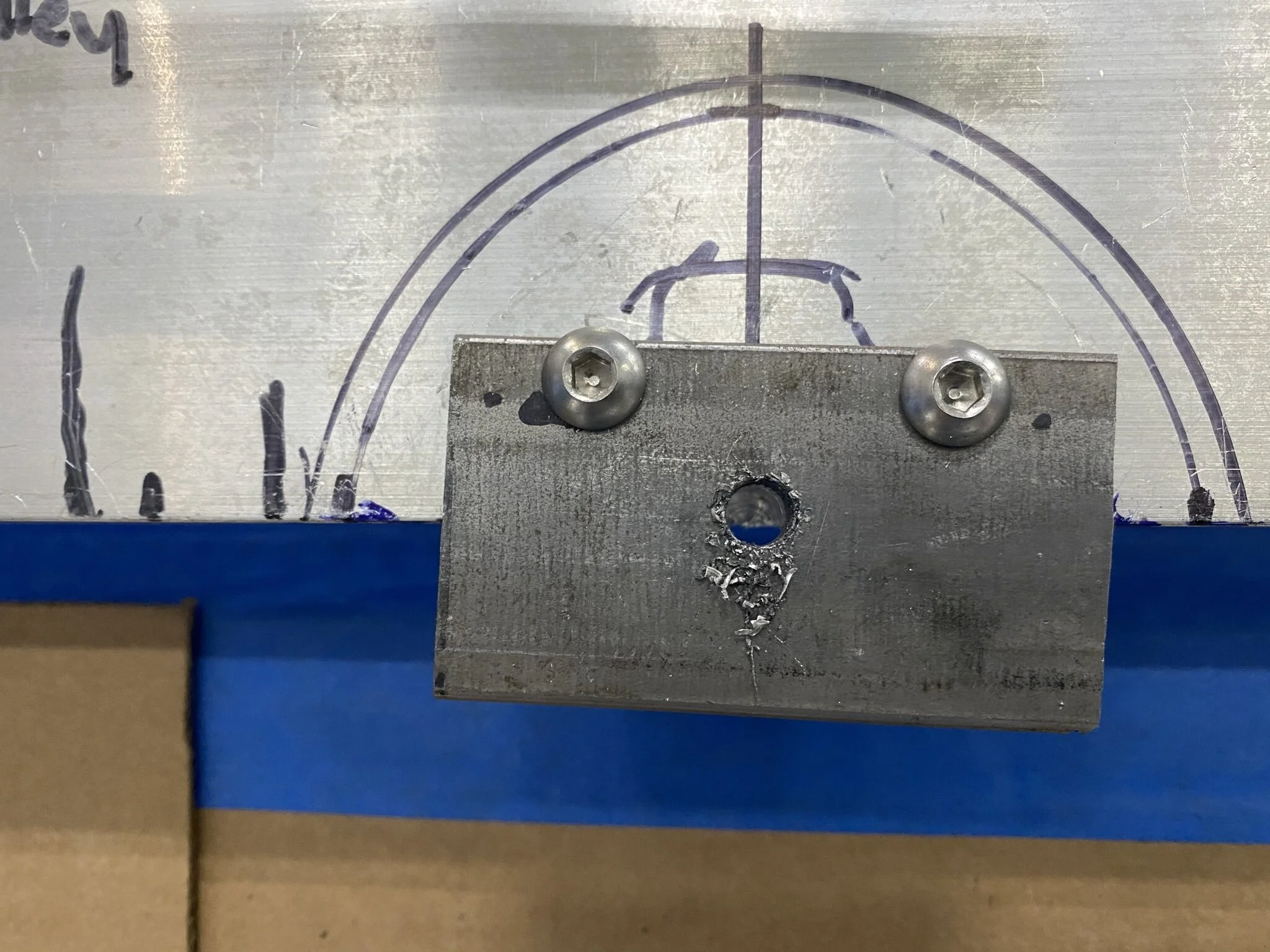
To ensure that the final welding of the flanges didn’t distort the geometry, a jig was fabricated. The jig plates that bolt to the flanges are made from 1/2” x 4” mild steel. They are intentionally heavy to prevent warping and to act as a heat sink. I designed the flange under the oil pan so I already had its hole pattern in CAD, but I wasn’t able to find the bolt pattern for LS7 heads so I had to figure it out. Hopefully the measurements below will be useful to someone. I think that they’re the same for all of the LS blocks with the LS3 having an additional hole. The measurements on the top indicate the exhaust flange bolts and the ones on the bottom indicate the center of the runners. These measurements made it easy to drill the holes using the DRO on the mill. Note that the two holes in the middle have different vertical values than the rest of the holes.
LS exhaust flange bolt and primary pattern
Oil pan (top) and header (bottom) exhaust flange welding jig plates
Stainless steel tube needs to be back purged with argon and both ends of the primaries were covered by the welding jig plates. To address this, I drilled and tapped a 1/8” NPT in the center of each runner to accept a brass tube fitting.

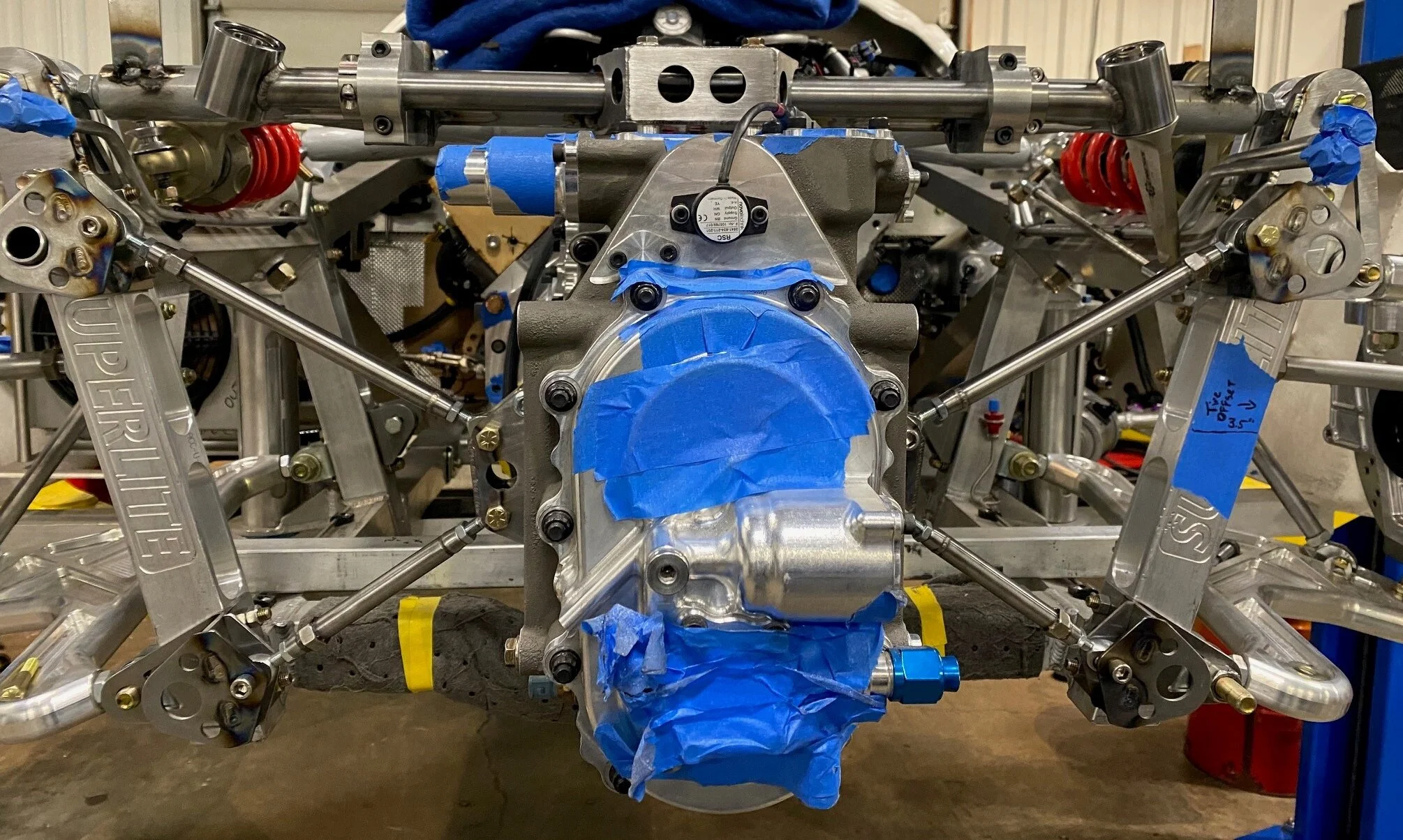
Left header mounted to the welding jig and a back purge hose connected to one of the primaries. Hex-drive flat-head screws were used on the bottom flange to provide more room for welding. I only had long screws on hand, so that that’s what we used
The right header will be easier to fabricate because the flange under the oil pan provides a solid target to finish the right side;
Cut and tack the remaining two primaries on the right side
Remove the four right primaries and finish weld them on the bench
Reinstall the right primaries and tack weld them to the flanges
Tack weld a temporary stainless steel rod to the top of the header flanges
Fabricate a second welding jig
Finish welding the flanges
Remove the stainless steel rod
… and pray that it all fits LOL